Gallery
Near-Surface Streaks
This video shows a horizontal cross-section of the temperature field from a direct numerical simulation (DNS) at a Reynolds number 104 (2 or 3 meters above a grass surface in a 1000 m deep boundary layer resolved to 2 m). Turbulence organizes into coherent structures of different sizes. Near the surface, streamwise rolls induce long streaks of fluid properties that align with the mean wind. In this case, this organization is illustrated by means of the high temperature sheets of ascending fluid that bring upwards the air heated at the surface (upwards means perpendicularly to the screen towards the viewer). The mean wind goes from left to right and the data corresponds to the same simulation shown in the video “Temperature in the Planetary Boundary Layer” in this same channel. You can find more information in Haghshenas and Mellado, “Characterization of wind-shear effects on entrainment in a convective boundary layer”, J. Fluid Mech., 858, pp 145-183 (2019). The simulation was performed at the Jülich Supercomputing Centre, GCS project HHH07.
Mixed Convection
This video shows a vertical cross-section of the temperature field from a direct numerical simulation (DNS) at a Reynolds number 104 (equivalent to a 1000 m deep boundary layer resolved to 2 m). The conditions are similar to those in the video showing the water vapor content, except that there is horizontal wind of about 15 m/s in the free atmosphere. This has major effects. First, one can see a more localized mixing at the boundary-layer top in the form of billows and braids between them. Second, a similar shear-driven forcing is observed near the surface. Nonetheless, convection dominates mixing in the boundary-layer center, and mean profiles are still approximately height-independent. One second of simulation corresponds to about 45 sec in nature. You can find more information in Haghshenas and Mellado, “Characterization of wind-shear effects on entrainment in a convective boundary layer”, J. Fluid Mech., 858, pp 145-183 (2019). The simulation was performed at the Jülich Supercomputing Centre, GCS project HHH07.
Convection Cells in the Planetary Boundary Layer
This video shows a vertical cross-section of the water vapor field from a direct numerical simulation (DNS) at a Reynolds number 104 (equivalent to a 1000 m deep boundary layer resolved to 2 m). It illustrates major characteristics of the planetary boundary layer (PBL) in unstable conditions, like it occurs during midday over land. We see how moist surface plumes (greenish color) converge and aggregate into updraft motions, which form the ascending branch of large convection cells. This ascending fluid eventually impinge into the capping inversion at the top of the PBL, entraining dry air from the free troposphere (brownish color) into the PBL. The flow diverge at the top, and converge into the downdraft motions, which form the descending branch of the large convection cells. Through these downdrafts, entrained air can affect properties across all PBL, even near the surface. You can find more information in Mellado et al., “Moisture statistics in free convective boundary layers growing into linearly stratified atmospheres”, Q. J. R. Meteorol. Soc., 143, 2403-2419 (2017). The simulation was performed at the Jülich Supercomputing Centre, GCS project HHH07.
Stratocumulus Clouds
This video shows the liquid water in two vertical planes (the cloud), and the vertically integrated liquid water at the bottom plane, from direct numerical simulations (DNS) at a Reynolds number 104 (equivalently, 800 m deep boundary layer resolved to 1 m). It illustrates the small-scale mixing at the top of the stratiform cloud that caps the planetary boundary layer. This type of simulations are extremely difficult because too coarse resolutions artificially enhance mixing with the dry and warm air in the free troposphere above the cloud, making the cloud disappear. In fact, this is the first direct numerical simulations of such a problem, reproducing measurements without having to tune the simulations for it. You can find more information in Mellado et al., “DNS and LES for simulating stratocumulus: Better together”, J. Adv. Model. Earth Syst., 10, 1421-1438 (2018). The simulation was performed at the Jülich Supercomputing Centre, GCS project HHH07.

This image corresponds to the logarithm of the enstrophy of a two-dimensional version of the same problem as before but with 4 times the resolution in the horizontal and vertical directions, which means 20480x5120 grid points. The physics of 2D and 3D turbulence are different, but this study provides a first estimate of some flow properties. You can find more information in Mellado et al., “DNS and LES for simulating stratocumulus: Better together”, J. Adv. Model. Earth Syst., 10, 1421-1438 (2018).
Air-Water Interface
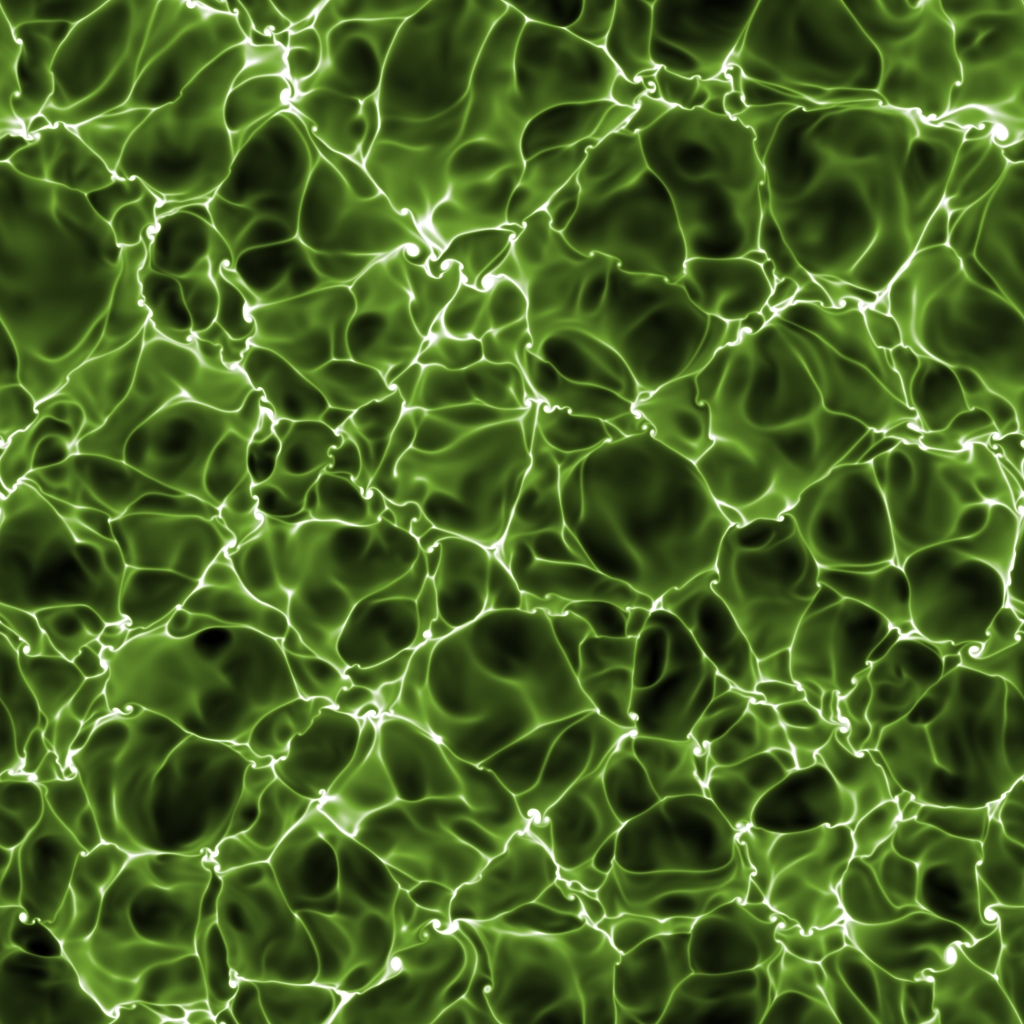
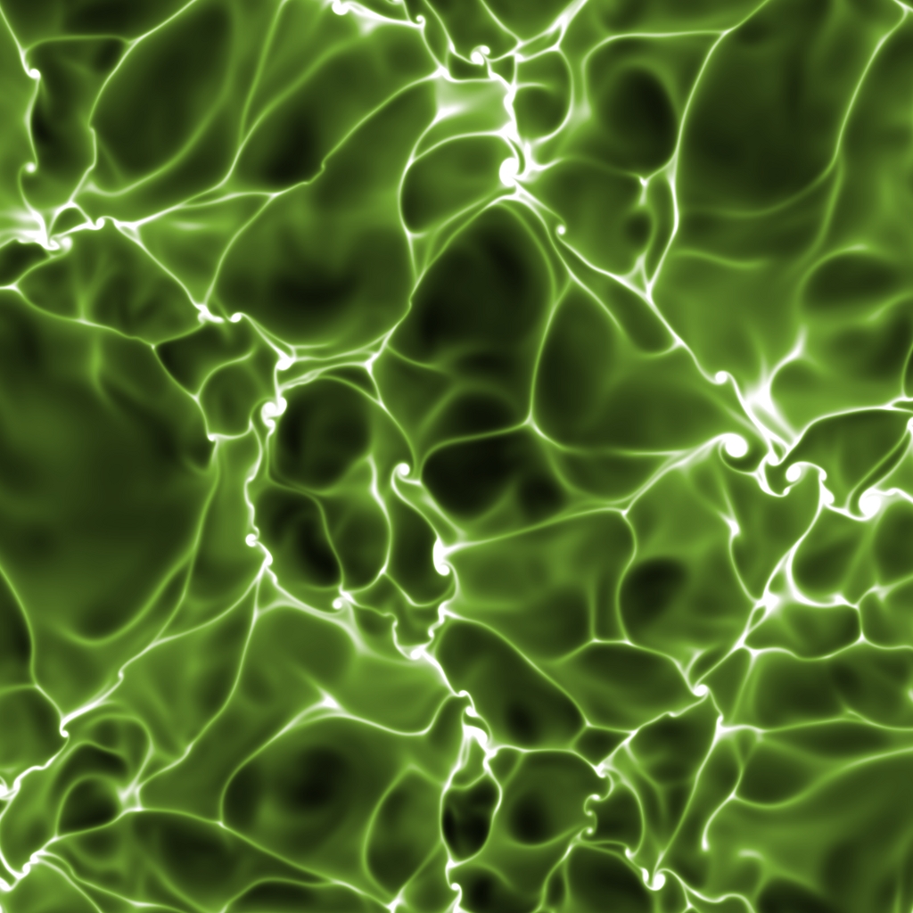
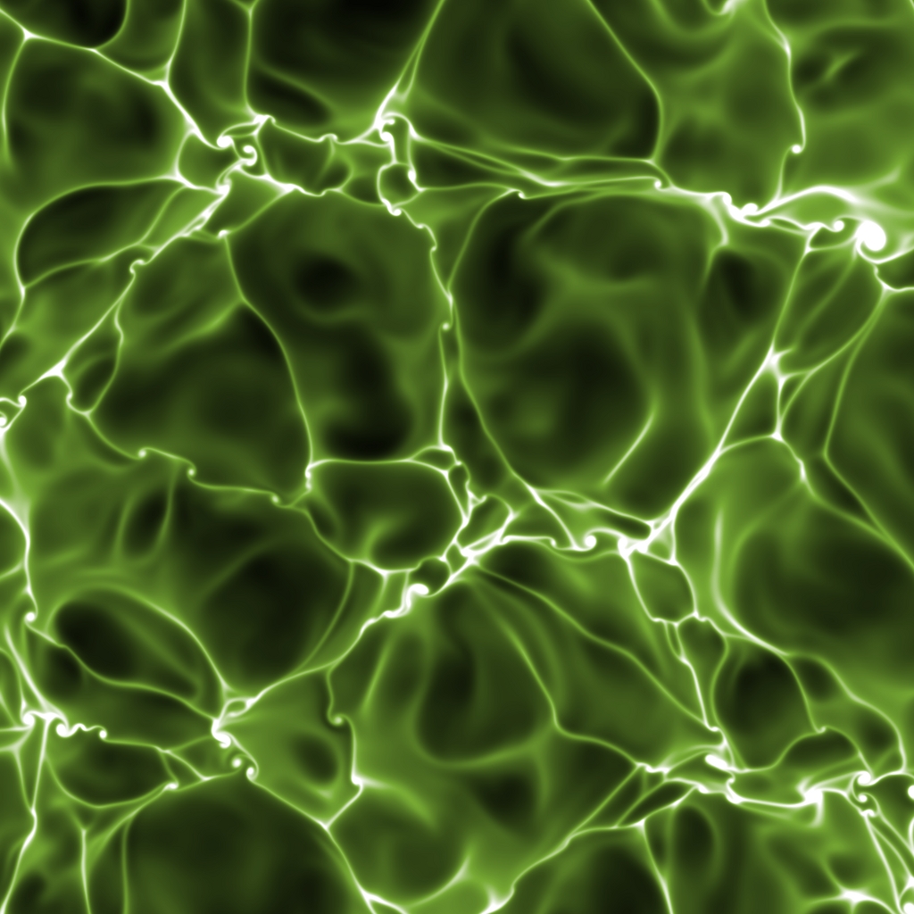
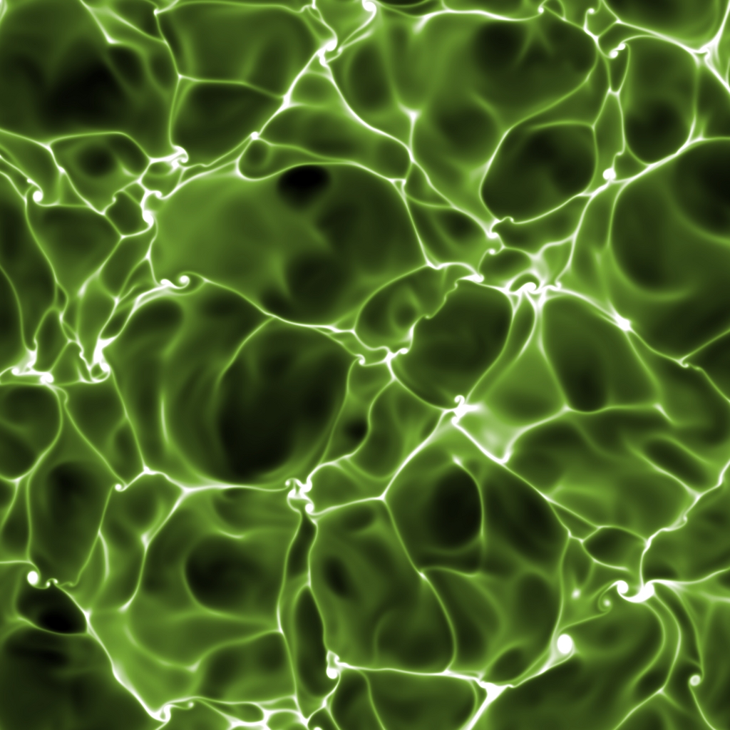
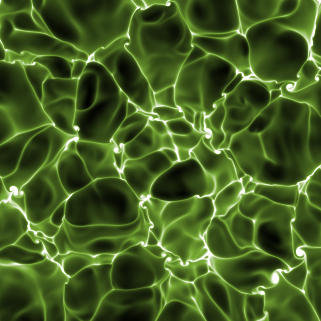
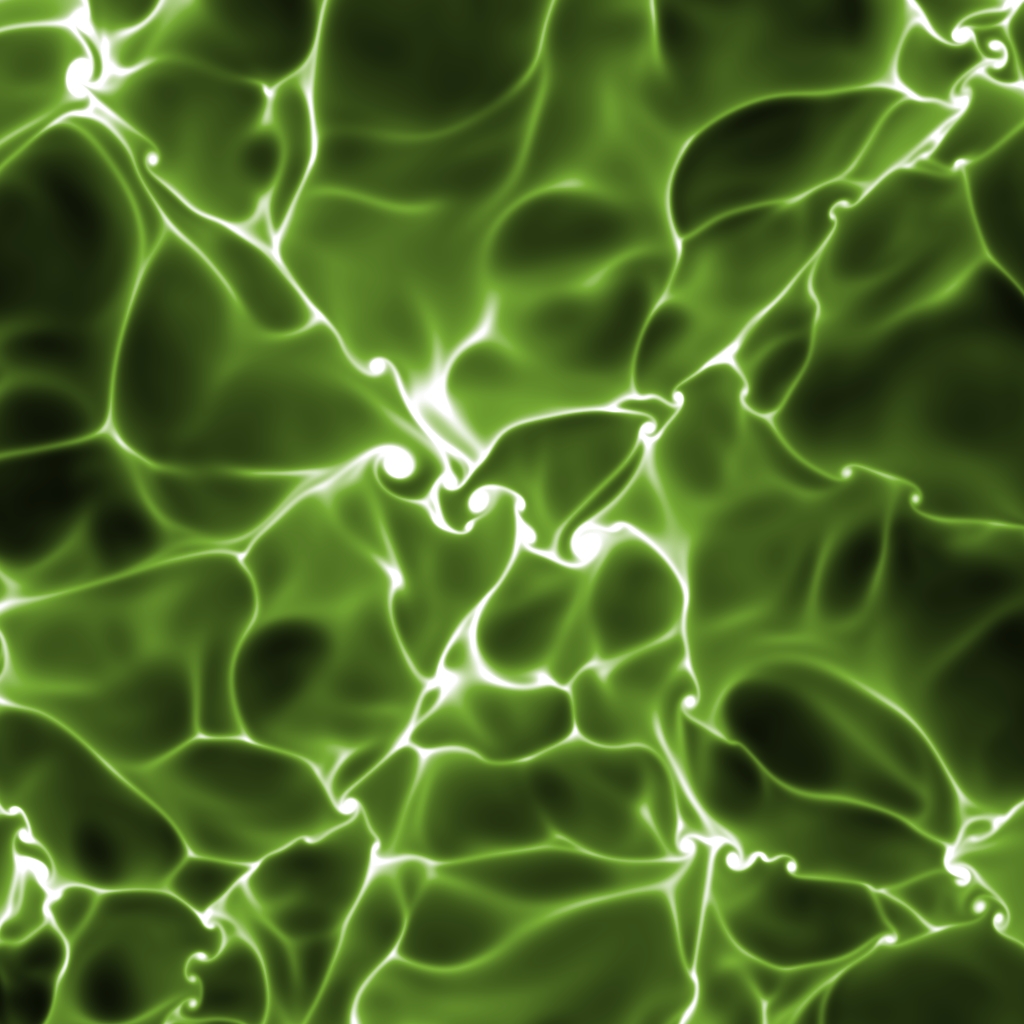
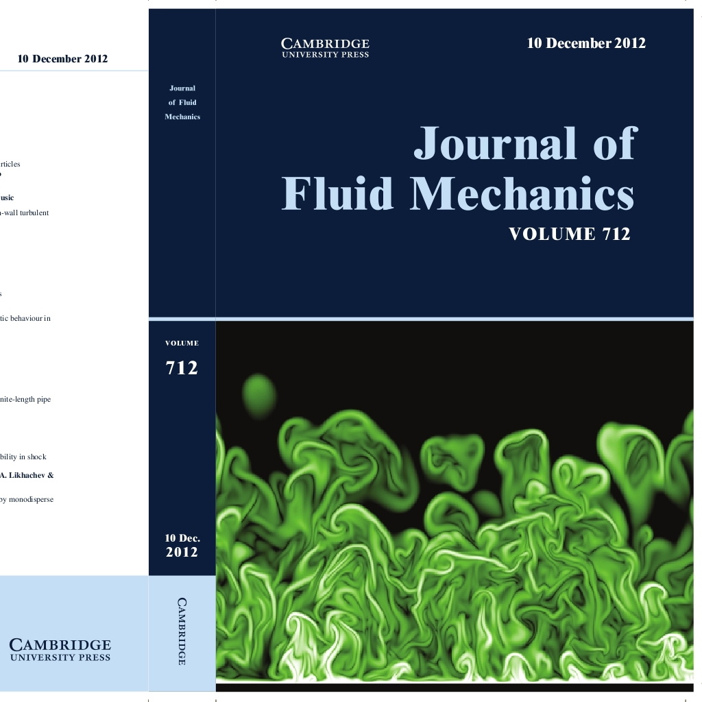
The fluid motion at the interface between the oceans and the atmosphere is crucial for their interchange of mass (constituents), momentum and energy. This series of images show the temperature field at the water-air interface, looking from above. The turbulent motion inside the water is caused by surface cooling. The center of the cells, in dark, corresponds to relatively warm regions ascending towards the surface (moving out of the screen). The brighter contours of the cells, only millimeters wide, indicate water a few degrees colder, plummeting as thermal sheets. The observed cellular pattern is typical in buoyancy-driven flows – it is the signature of ordered motions amid random fluctuations. You can find more information in Mellado, “Direct numerical simulation of free convection over a heated plate”, J. Fluid Mech., 712, 418-450 (2012).
Cloud-Top Boundary
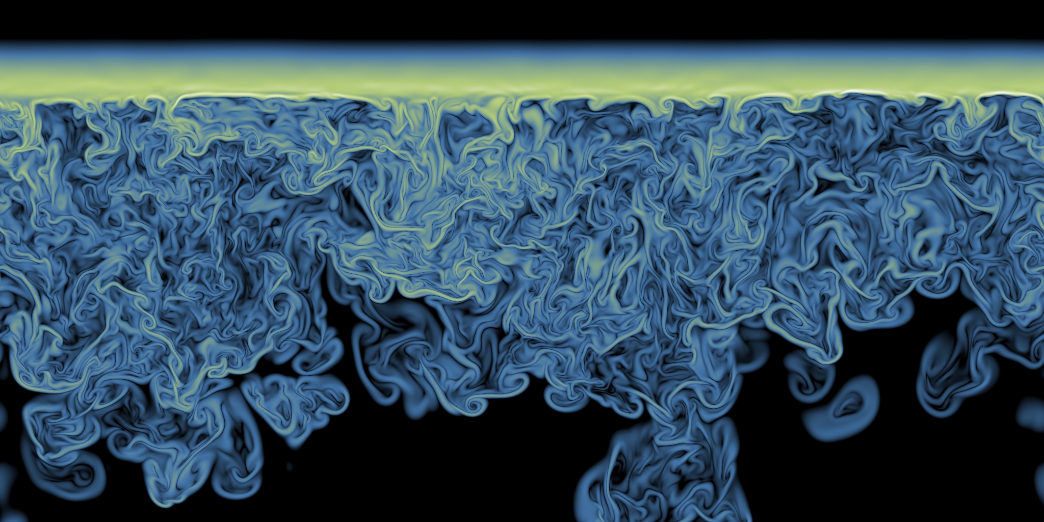
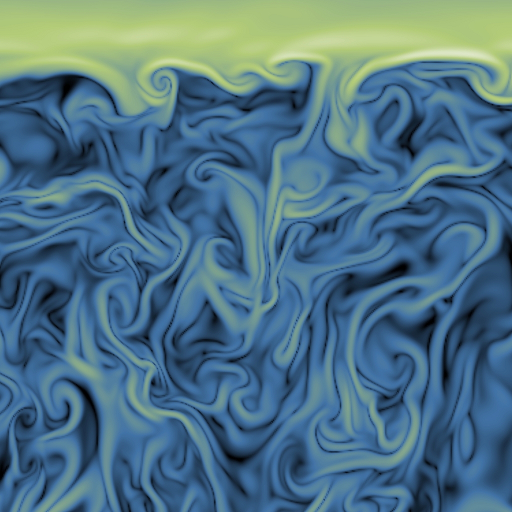
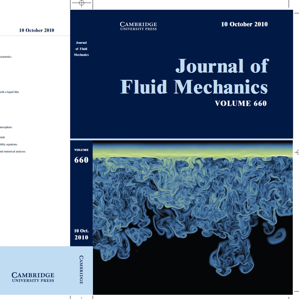
Mixing at the cloud boundaries play a fundamental role in the evolution of clouds, and clouds can have in turn a profound impact on planetary scale circulations. This image depicts the turbulent structure of the stratocumulus cloud-top inside a vertical plane in terms of the magnitude of the temperature gradient, resolving scales from 4 meters down to about 4 milimeters. The upper horizontal stripe corresponds to the inversion that separates the turbulent cloud below from the warm clear sky above. The turbulent motion is created by the evaporation of the droplets in a thin region next to that inversion, which cools locally the fluid mixture and leads to finger structures plummeting into the cloud. You can find more information in Mellado, “The evaporatively driven cloud-top mixing layer”, J. Fluid Mech., 660, 5-36 (2010).
Turbulence Intermittency
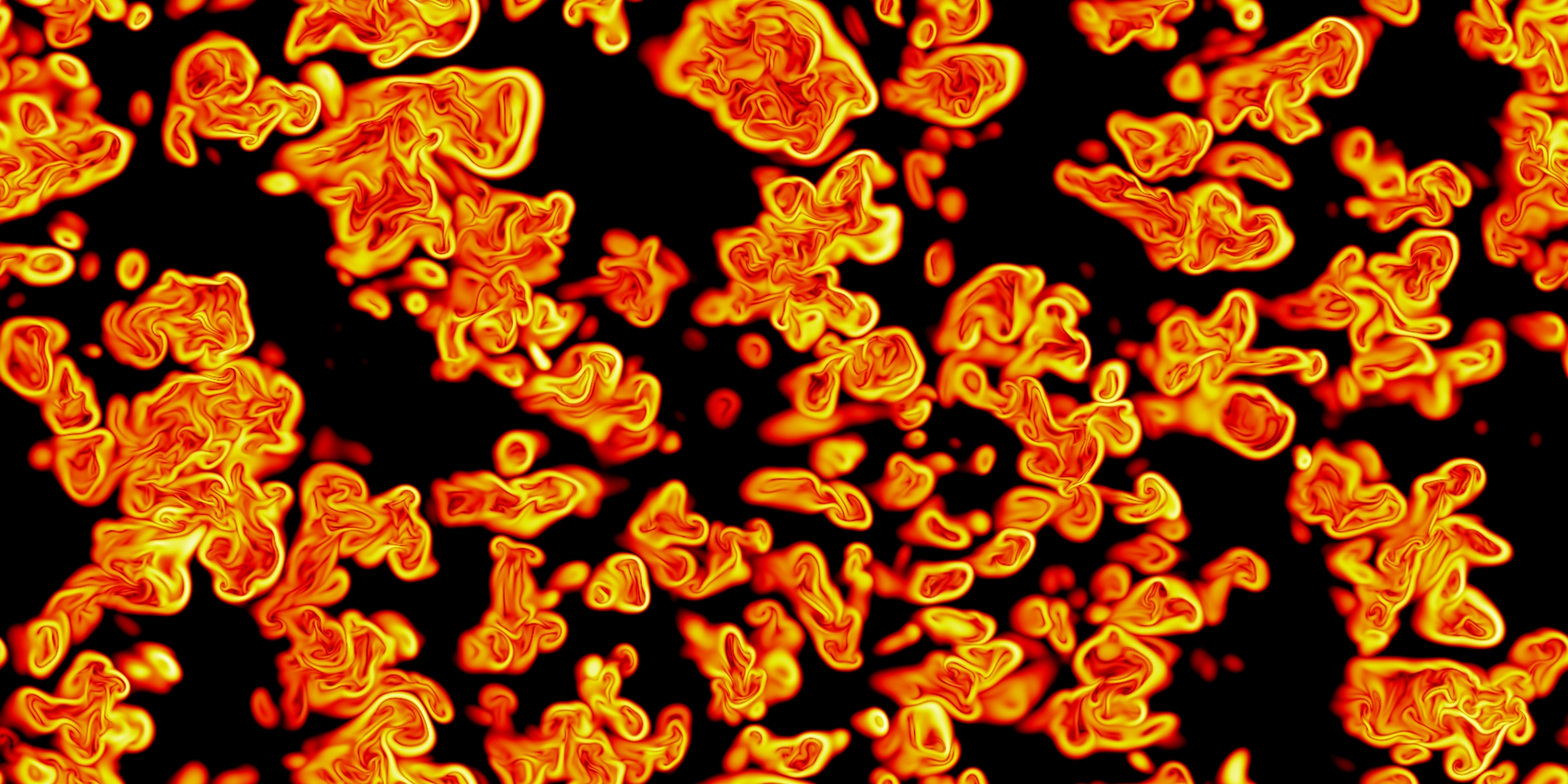
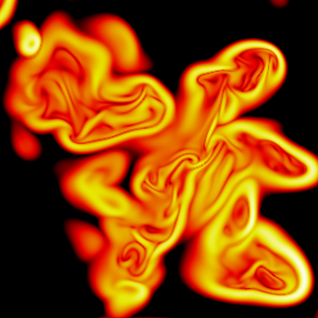

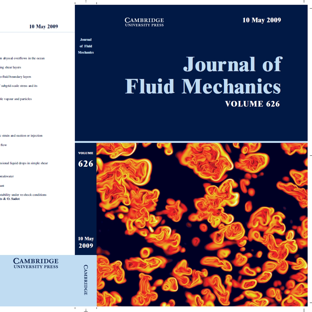
Measurements in external turbulent flows are characterized by an alternation between intervals with a rapidly varying signal and intervals with a slowly varying signal, or even complete calm, depending on the property being measured. This feature is referred to as (outer or external) intermittency and it reflects the coexistence of turbulent and non-turbulent regions. This figure illustrates this property in terms of the scalar gradient inside a horizontal plane in the upper part of the mixing layer that develops as a consequence of the relative motion of two superimposed regions (fluid flows from right to left). We can see very clearly the strong and sharp boundaries that separates the turbulent patches from the black, non-turbulent region. You can find more information in Mellado et al., “Gradient trajectory analysis of a scalar field with external intermittency”, J. Fluid Mech., 626, 333-365 (2009).